


Installation of over voltage protection in LV systems
Author: Denis Imširović, B.SC.E.E.
From old times the human beings have been fascinated by the lightning phenomenon, but unfortunately they were unable to explain it. Nowadays, in the era of computers and other sensitive devices it has become necessary to expand technical possibilities for successful or complete protection of vitally important services.
1. Introduction
Technology is entering into the future with big steps; therefore the devices are installed into the areas where can not be imagine a while ago. An enormous quantity of information is used
over the world, which must be properly connected, reach faster transfers and use best possible protection. Now days especially in such an economically and technically developed world
there is no possibility to refuse those demands. Over voltage protection must be considered, as hard cuirass which protects devices and people against strong outside influences, as stroke of
lightning and prevent technological and economical damage.
Over voltages are caused because of following:
- Atmospheric discharges resulting in direct strikes to structures or systems, or large induced voltages caused by those direct strikes
- Over-voltage cause by power switching transients
- Faults in power distribution systems such as line-to-ground contacts, or commingling of power and low voltage telecommunication lines
- Power regulation faults as can occur near large industrial consumers of power or near electrified rail systems
The statistic of damages caused on electrical apparatus is demonstrated in below graph (Picture 1). The biggest share damage on electrical apparatus is caused because of over voltages and ranges between 27% and 35%.
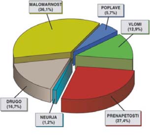
Picture 1: Ratio of different damage causes
2. Installation of over voltage protection
Manufacturer can produce very quality product, but in case surge protection device is installed incorrectly into the system, there is no assurance for proper protection. Different type of surge protection devices are used according to the different network systems; therefore it is very important to ensure that surge protection device is correctly selected and coordinated with the type of power system in use and any over-current protection devices installed.
To reach maximum level of protection, following points must be considered:
- proper selection of surge protection device according to the network system
- to create more levels of protection,
- consider the length of the ground conductors.
- define voltage protective level Up.
2.1. Different type of impulses and currents
Before starting to write down on paper, define and even discuss about over voltage theme, defined supposition were needed. Simulation of short peak over voltages and atmospheric
discharges demand precise definition of short current peaks and short voltage peaks. Standard IEC 61643 describe three types of impulses:
- energy current impulse 10/350,
- current impulse 8/20,
- voltage impulse 1,2/50.
Energy current impulse 10/350, Iimp
Direct strikes can be simulated with energy current impulse 10/350. It is used to define Iimp current also, which can be according to IEC 61643 standard used, as energy current impulse for testing surge protection devices class I. According to standard the time 10μs is rise time of energy current impulse from 10% up to 90% of value, meanwhile 350μs is fall time from 90% to 50% of value. Standard allows 20% of deviation also.
Current impulse 8/20, In and Imax
Indirect strikes can be simulated with current impulse 8/20. It is used to define In and Imax. and both currents according to IEC 61643 standard can be used, as current impulse for testing surge protection devices class II. Maximum current, Imax represent double value of nominal current, In or according to different manufacturer technical data. According to standard the time 8μs is rise time of current impulse from 10% up to 90% of value, meanwhile 20μs is fall time from 90% to 50% of value. Standard allows 20% of deviation also.
Voltage impulse 1,2/50, Uoc
Surge protection devices class III are tested according to the IEC 61643 standard with combine waves, voltage 1,2/50 and current wave 8/20. The combination wave is delivered by a generator that applies a 1,2/50 voltage impulse across an open circuit and an 8/20 current impulse into a short circuit. Voltage impulse is defined, as Uoc and current at short circuit as Isc. Standard define time 1,2μs as rise time of voltage impulse from 30% up to 90% of value, meanwhile 50μs is fall time from 90% to 10% of value. Standard allows 20% of deviation also.

Above picture (picture 2) illustrate the difference between current impulses shape of waves 10/350 and 8/20. Square dimension under curve can be imagining, as energy of the strike. According to energy equation or Joule integral easy calculation can be done to proof that energy at direct strike is much higher.
Calculation:
I2 x t
Direct strike; Indirect strike;
I2 x t = 25kA2 x 350 x 10-6s = 218kJ I2 x t = 5kA2 x 20 x 10-6s =500J
2.2 Determination of voltage protective level, Up
Up, voltage protective level, which appears at surge protective device’s terminals at presence of impulse with exact shape and amplitude. Main rule at surge protective device connection is to mount and connect it between phase and ground conductor (PE or PEN) or parallel to the protected element, as shown on below picture (picture 5). When atmospheric discharge or short peak voltage appears preliminary characteristics of installed varistor changes shape and arrestor goes to conducting stage. Reaction can be imagining, as closing switch and superfluous current flows into ground. Installed varistor is non-linear resistor and under normal condition it has very big resistance, at short peak voltage or atmospheric discharge the situation becomes inversely, it means low resistance and conducting stage – all superfluous energy leads to the ground.

The goal of over voltage protection is to reach lower value of voltage level, as dielectric withstand of protected equipment. According to the standard IEC 61643 devices are divided into four groups-categories. Dielectric withstand must be given by the each manufacturer.

2.3. Proper length of ground conductors
Main cause for irregular function of over voltage protection elements is un-considering the length of ground conductor PE, PEN. The length of the conductors influences additional inductive voltage drop as follows; a conductor length of 1m has an inductance of approximately 1μH, which at current steepness of 1kA/μs contributes approximately 1kV. Difference of voltage which appears because of additional conductor length must be considered with arresters Up voltage level, when reaching proper result.

Therefore the surge protection devices must be installed with the sense of decreasing the length of connected conductors between phase and ground terminals. Example on next page (picture 8) demonstrate proper way of mounting and maximal conductor length. Cross-section of ground conductor must be considered, as following:
- class I: minimal 16mm2,
- class II,III: minimal 6mm2.

2.4. Protecting zones and creating higher level of protection
Protecting zones and cross points of protecting zones, where over voltage protection is installed are provided by the manufacturer. Protecting zones are divided into three levels. Places or connection points are: MB, SB in SA.

At point MB (main distribution board) which is at crossing OB/1 and is subject to partial direct lightning strikes class I surge protection devices must be installed. Class I surge protection devices are those declared for current arrester pulses 10/350 μs. At point SB (sub distribution board) which is at crossing 1/2 and is subject to indirect lightning strikes class 2 surge protection devices must be installed. Class II surge protection devices are those declared for current arrester pulses 8/20 μs. At point SA (socket outlet) which is at crossing 2/3 and is subject to indirect lightning strikes, a class III surge protection devices must be installed.
Class III surge protection devices are those declared for combined voltage pulses 1,2/50 and current pulses 8/20. Arresters class III are used, when very sensitive equipment is intended to protect, with dielectric withstand category IV and it is installed always behind arresters class I, II. When secondary or cascade level of protection is chosen, the manufacturer must provide table of Up values.
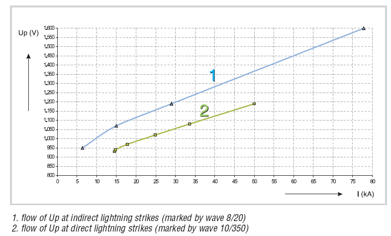
Picture 9: Diagram of characteristic values Up (kV) in dependence of current (kA)
2.5. Proper installation of protection according to the network systems
For proper installation the over voltage arrester must be mounted into the system between phase (L) and ground conductor (PEN, PE). In TN-S and IT systems surge protection device must be installed between neutral N and ground conductor PE either. In TT systems special rule is valid; it means gas discharge tube must be installed between neutral N and ground PE conductor. Gas discharge tube is needed in case of phase-ground connection the high potential is transferred to the earth and housing of apparatus, which is not connected to the same potential level may present risk for human life. Gas discharge tube installation reaches galvanic separation between conductors and breaking of electrical circuit in first period.
 |  |
| Picture 10: TNC-S system connection | Picture 11: TNS system connection |
 |  |
| Picture 12: TT system connection | Picture 13: IT system connection |
3. CONCLUSION
To reach maximum over voltage protection of equipment, at least above mentioned parameters must be considered. The theme over voltage protection is day by day closer to our lives, because of human nature, which is a cause, that short peaks voltages appears more and more into our homes. A fact is, that LV over voltage arresters represent big business potential, because some of countries put already a regulative that every new electro installation must include over voltage protection as well.