

E-mobility: Electric chargers - part 2
The most efficient and safest method for charging electric vehicles for home use in accordance with the IEC 61851-1 standard is AC mode 3, either a single-phase or three-phase connection with different power ratings.
| Aleksander Cilenšek Product manager |
In the previous blog on the topic of electric charging stations, we presented you with different options for charging electric vehicles. This time, however, we will show you how a basic home charger (Wallbox, Mode 3) is built for home use, which are the basic and most necessary components inside, how it communicates with an electric vehicle and what a type 2 socket and plug look like.
Home EV charger – mode 3
If we imagine a wallbox charger with a fixed cable and a type 2 plug (Figure 1, A), the question immediately arises: how does the charger signal to the car how much current it can “draw” to charge the battery, so as not to overload the connector or the electrical installation, and how does the charger detect when the car is plugged in and whether it is even charging? For this purpose, the plug has a communication pin marked CP (control pin). This pin is used by the charger to detect whether the vehicle is plugged in, ready to charge and the charging status with the voltage ranges (the resistive potential divider in the vehicle). At the same time, the PWM signal, which signals to the car with the duty cycle how much current it can draw (Figure 2), is also transmitted through it. The voltage levels and duty cycles are specified in the IEC 61851-1 standard. There are home chargers on the market with an adjusted charging current or dynamic chargers. Dynamic ones can be connected to an electricity meter or to a current instrument transformer, which measures the total consumption at the house connection to regulate the charging current and prevent overloads and unwanted shutdowns.

Figure 1: Example of home (A) and public (B) wallbox charger according to mode 3, the type 2 portable cable (C) for connecting to an AC public charging station

Figure 2: PWM-signal on pin CP, above for 16 A (duty cycle =27%), below for 6 A (duty cycle = 10%)

With DC charging, the power is not constant, depending on the temperature and battery charge
However, in the case of Mode 3 public chargers (Figure 1, B), where the user plugs in an electric car with a portable cable (Figure 1, C), the charger needs to detect the capacity of the cable to avoid overloading it. There are cables on the market for different charging capacities (power), e.g. 3.7, 7, 11 and 22 kW. These chargers usually have a type 2 socket with a lock, since a loose exterior cable poses too high a risk of damage or theft as it contains valuable copper. The charger “checks” the capacity of the cable via a dedicated PP pin to which the grounding resistor is connected. This resistance determines the maximum permitted charging current to ensure that the cable is not overloaded. The resistor values and their meanings are also defined in the standard (IEC 61851-1). Figure 3 shows the pin layout for a type 2 plug according to IEC 62196-2. For a house charger with a fixed cable, the CP pin will be installed on the plug while the PP pin will be installed on a stand-alone cable intended for connection to a public charging point, or both. In the case of a 1-phase system, pins L2 and L3 are empty. Due to the CP and PP communication pins, there is an auxiliary cable within the communication cable and therefore a standard 1-phase (3-core) or 3-phase (5-core) cable is not sufficient. There must be no voltage in the cable and plug until the charger detects that the car is connected and ready to charge. The charger will also immediately switch off the power supply in less than 100ms when it detects that the charging is over or when the circuit is suddenly interrupted.

Figure 3: Type 2 socket for charging mode 3
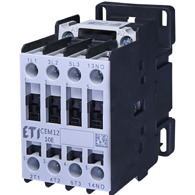
A dedicated EVSE control relay is integrated into the charger for communication with the electric car and for charging management/control, which operates according to IEC 61851-1.
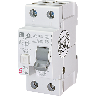
In addition to the instantaneous disconnection protection, the standard requires residual current protection with a sensitivity of 30mA, which must be at least type A with additional detection protection up to 6mA DC residual current or type B. The residual current protection may also be a combination of, for example, a Type A pre-protected electrical installation and an additional 6mA DC residual current protection in the charger. Many manufacturers of Mode 3 chargers have a solution with only the added electronic detection of 6mA DC and switching off via a contactor or relay when the EVSE controller detects a defect.
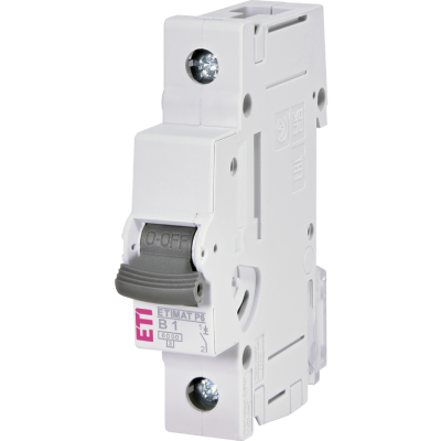
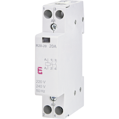
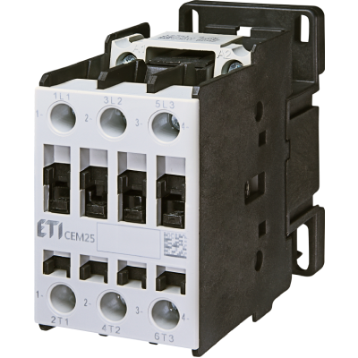
Figure 4 shows an example of a simplified electrical diagram, with an RCCB EV-type residual current switch (F1) at the charger input, followed by an IEC 61851-1 installation contactor (K1) and EVSE control relay (K3). The diagram could also include an RFID reader that allows charging when the user is recognised, a time relay that the installer can set to operate during cheap electricity tariffs, a communication module, an electricity meter, overvoltage protection, a voltage controller, etc.

Figure 4: Simplified electrical diagram of the charging station
What does the future hold in the field of development of home chargers? Smart chargers are already appearing on the market with built-in support for the open charge point protocol (OCPP). This protocol should allow the remote management of the charger for on-demand charging by the user, the electricity distribution company or a power management system. In some countries, government subsidies are available conditional upon support for this protocol, e.g. in the UK. There is also more and more talk of bi-directional chargers, where an electric car can become an energy storage device.
There are two ways to do this:
- vehicle to home (V2H), a two-way energy flow between an electric car and a household,
vehicle to grid (V2G), a two-way flow of energy between an electric car and the electricity grid.
This soon raises new questions, such as the relevance of continuous AC/DC and DC/AC conversion and the associated losses. We still do not have a definitive winner in the battle between Tesla and Edison yet, and we will soon have DC circuits in our homes.
Sources: ETI Leaflet: EV_smart_charger.pdf